There is a certain charm to older electronics gear. Heavy metal chassis and obviously hand-wired harness can be a work of art even if they would be economically impractical for most modern gear. Watching [msylvain59’s] tear down of a Collins 51R VOR receiver is a good example of that. The construction looks so solid.
If you aren’t familiar with VOR, it stands for VHF omnidirectional range and allows airplanes to tune into a fixed ground-based beacon and determine its heading in relation to the beacon. In some cases, it can also calculate distance.
Years ago, VOR antennas actually rotated rapidly, but today it is more likely to be an array of antennas switched electrically. The radio beam has several encoding schemes, including an FM reference signal that allows an airplane receiver — like the 51R — to determine the heading to the beacon. If you know the heading to two beacons, you can figure out where you are. Even with a single beacon, you can hold course towards it or away from it if you maintain a steady heading.
A receiver like the Collins would drive a Course Deviation Indicator (CDI), a Horizontal Situation Indicator (HSI), and a Radio Magnetic Indicator (RMI) on the plane’s cockpit and might also provide input to an autopilot. Compared to modern gear, the components look huge.
Understanding where an aircraft is has always been a big deal, and there are many ways to deal with it. Transponders are one part of the equation. We see a lot of hacks relating to ADS-B, too.
I suppose most of us have had the experience of going to the mailbox and seeing that telltale package in the white plastic bag, the sign that something has just arrived from China. This happened to me the other day, and like many of you it was one of those times when I puzzled to myself: “I wonder what I bought this time?”
With so many weeks or months between the time of your impulsive click on the “Buy Now” button on AliExpress or eBay and the slow boat from China actually getting the package to your door, it’s easy enough to forget what exactly each package contains. And with the price of goods so low, the tendency to click and forget is all the easier. That’s not necessarily a good thing, but I like surprises as much as the next person, so I was happy to learn that I was now the owner of a tinySA spectrum analyzer. Time for a look at what this little thing can do.
First Impressions
A caveat: I’m by no means an expert on spectrum analyzers. In fact, this is the first time I’ve ever handled one, unless you count using the FFT functions in my digital oscilloscope, which you probably shouldn’t. So there’s probably plenty of room for operator error and misconceptions about what a spectrum analyzer can do in the tests that I ran, but I still think this is valuable as an example of what a tool like this can do in the hands of an enthusiastic newbie.
Anyone familiar with the NanoVNA, a small but full-featured vector network analyzer that we’ve featured a few times on these pages, will see a strong family resemblance between it and the tinySA, both in the hardware and the software. That’s for good reason — the code behind tinySA is a fork off the NanoVNA codebase, and the main developer of NanoVNA, edy555, is a contributor to the tinySA project, which is owned by Erik Kaashoek.
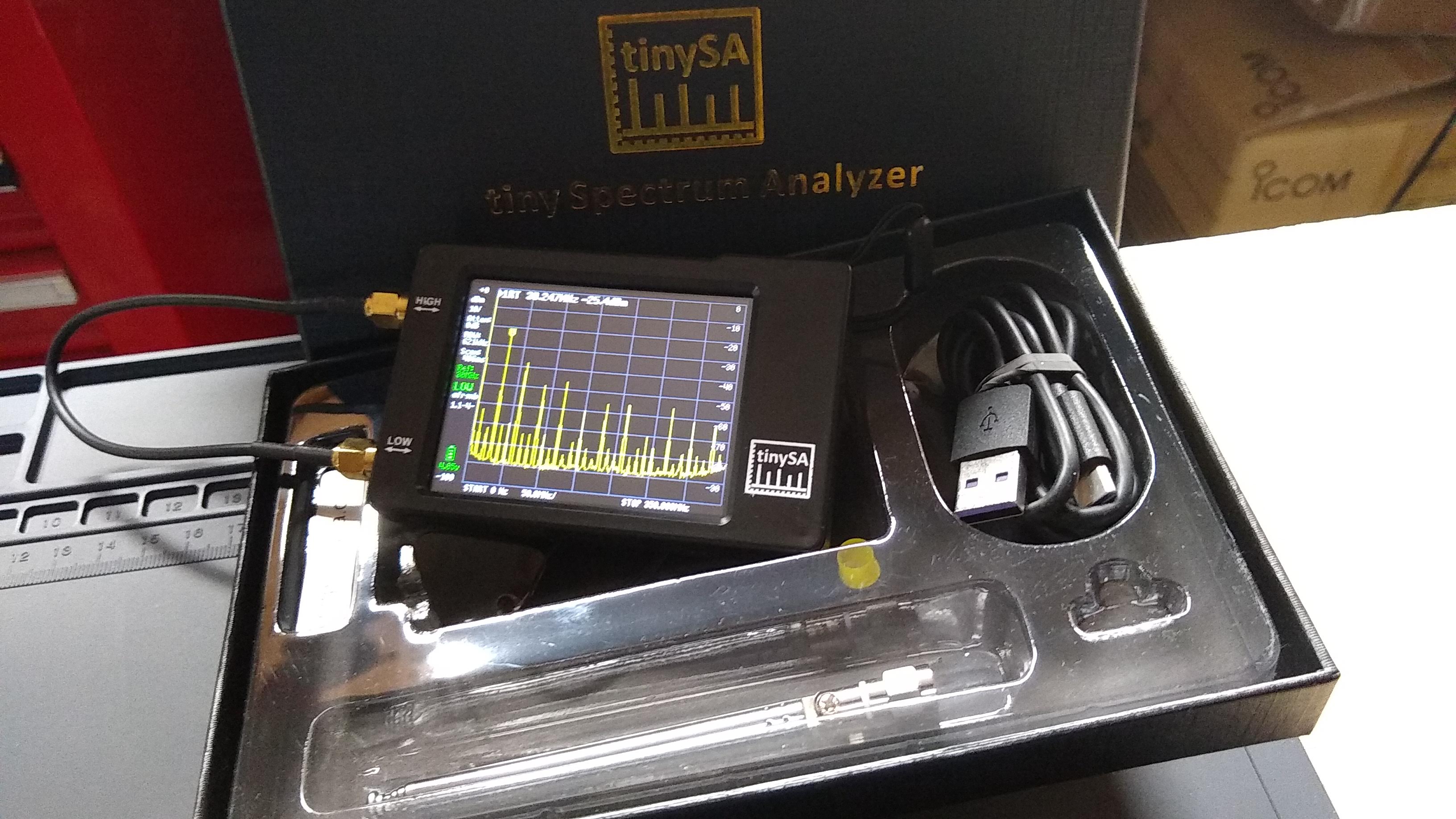
The tinySA arrived in a surprisingly nice “presentation quality” box with a gold-stamped logo on the top. Erik takes pains to note that this is one way to tell you’re getting an original tinySA as opposed to one of the inevitable knock-offs that’ll flood the market soon enough. I’m not sure that alone would keep the pirates at bay, but it’s at least an attempt and it’s a nice touch to boot.
Along with the tinySA, which is about the size of a deck of playing cards, the box contains a pair of SMA jumper cables, a small telescoping whip antenna, a female-to-female SMA adapter, a wrist strap, and a USB-C cable. The case of the tinySA is injection molded ABS, and a nice upgrade in look and feel from the open board design of the NanoVNA. The front of the tinySA has no controls, just the 2.8″ 320×240 resistive touch-screen display. The top has a power switch and a jog control. The left side has two SMA jacks, labeled HIGH and LOW. It’s very lightweight but feels solid in the hand.
A look inside the tinySA, with the RF shields removed.
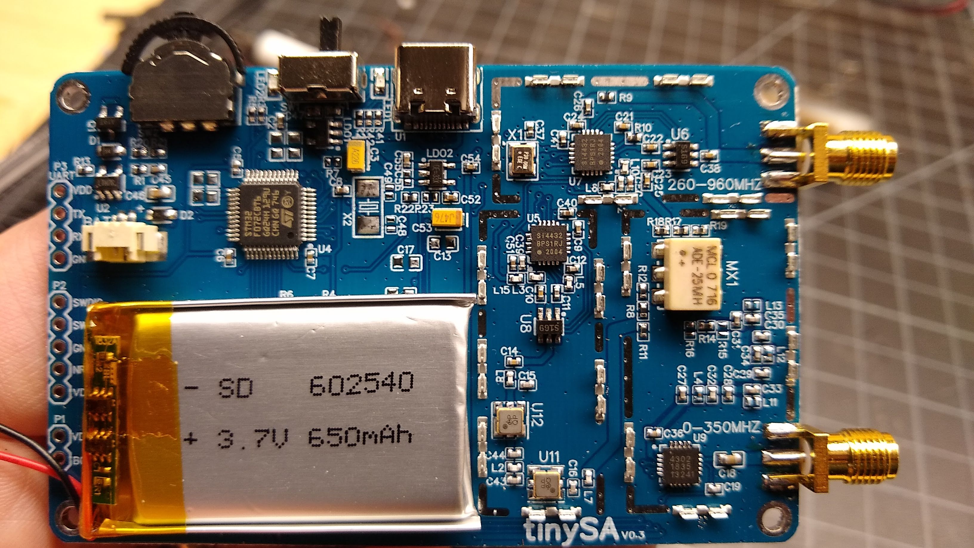
Of course the first thing I did was pop the case open and take a look inside. There’s not a lot to see at first — most of the interesting RF stuff is safely tucked under shielding. I figured I’d have to bust out the Hakko to take the tins off, but luckily they’re all spring-clipped to the ground plane, so removing them just took a small screwdriver. Underneath lay the expected RF wizardry, including the expected Silicon Labs chips. I found two Si4432 ISM transceiver chips, presumably one each for the high and low range of the tinySA. There’s also what appears to be a Peregrine Semiconductor PE4302 RF digital attenuator, and a bunch of other goodies. The layout is nice with plenty of via stitching, and the assembly quality is really good.
Satisfied with the insides, I moved on to the “First Steps” as listed in the video below, to get acquainted with the device. Erik has chosen to rely on the tinySA wiki and some how-to videos for most of the documentation, and while that’s understandable it also leaves a few holes that are up to the user to fill in. For those of us who prefer a real manual, Kurt Poulsen, a ham from Denmark, has written up a comprehensive how-to document that might be of help.
Anyone who has used a NanoVNA will feel at home in the tinySA interface. Calibration of the tinySA is done via the built-in signal generator, more on that below. Calibration itself is simple: hook the jumper coax between the two SMA jacks and select LEVEL CAL from the configuration menu. The calibration then proceeds automatically. The same menu offers a self-test function too, which cycles through a series of ten tests that take about 15 seconds to complete.
The Good Stuff
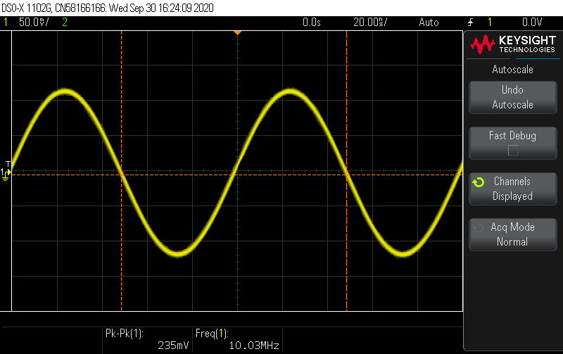
As for its primary purpose, the tinySA performed admirably in my limited tests. I took a look at the spectrum of signals generated by my scope’s built-in waveform generator and everything looked good — a 10-MHz sine wave appears as a single strong fundamental spike and one harmonic about 50 dBm lower. Switching the waveform to a square wave at the same frequency did what I thought it would — a big peak at the fundamental and a bunch of spurs at the odd fundamentals.
Output from the tinySA on my scope – solid, clean 10-MHz sine signal.
With the basics out of the way, I took a look at the tinySA’s built-in signal generator. As mentioned above, the signal generator is used for calibration, but it’s a pretty capable tool all on its own. It’s actually more of a function generator, since it can not only output a nice clean sine wave on the low output between 100 kHz and 350 MHz, but it can also modulate the signal (AM, narrow FM, and wide FM) and do sweeps both across a frequency range and over amplitude. On the high output, the signal generator does a square wave output from 240 MHz to 960 MHz with a configurable, non-sweepable amplitude, narrow FM or wide FM modulation, and a frequency sweep.
I gave the signal generator a go and took a look at its output with my Keysight DSOX1102G. The sine wave generated on the low output looked clean across the specified bandwidth, and the frequency was spot on. I tried playing with the modulation function, and it worked pretty much as I expected. It’ll be nice to have another signal generator around the shop.
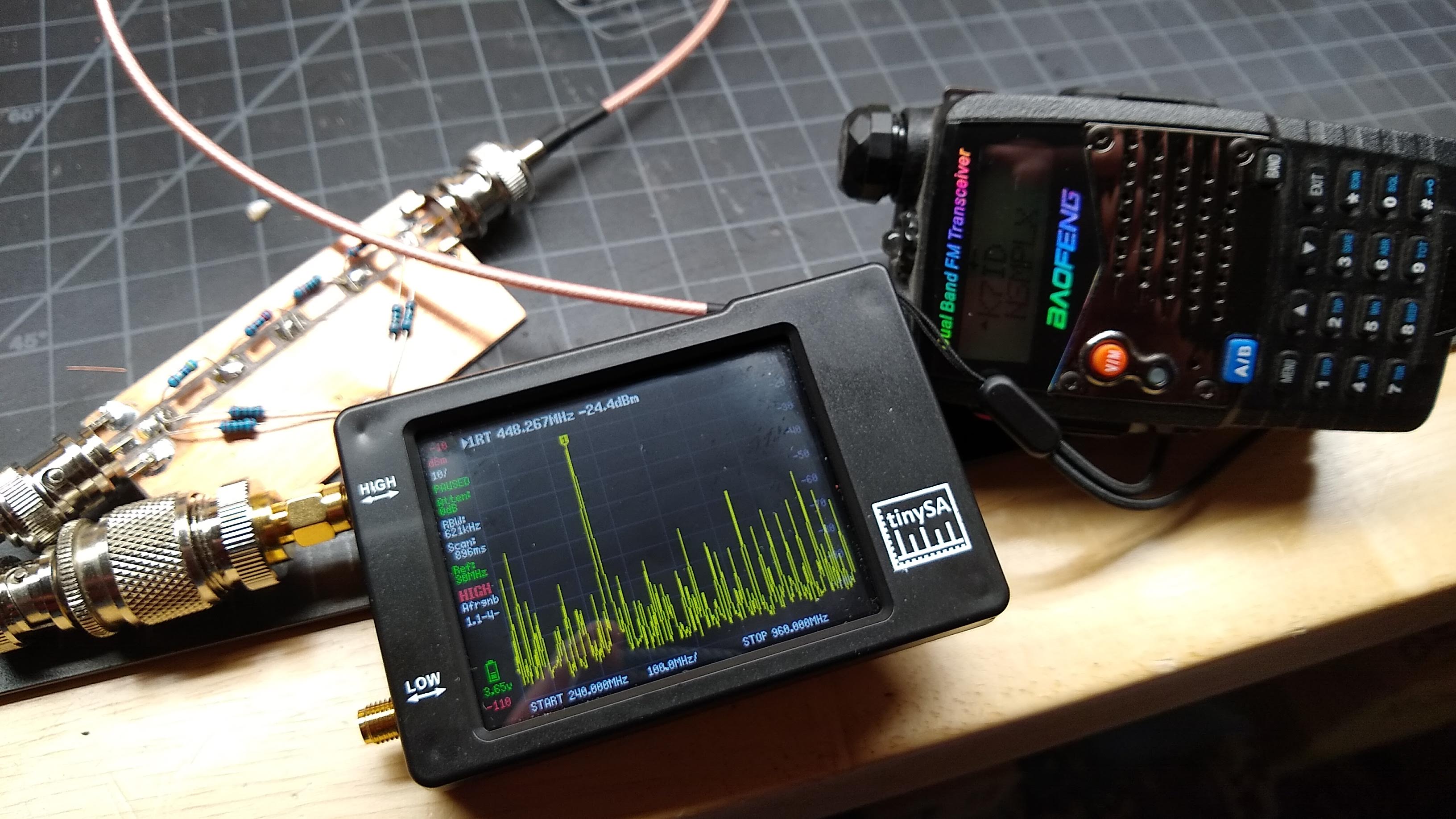
My janky test setup: UV-5RA, homebrew 40 dB attenuator, and the tinySA.
With all the pleasantries dispensed, I turned to the one task pretty much every ham will want to turn a spectrum analyzer on: finding out just how bad the signal from a cheap handy talkie is. I talked about this a bit in one of my $50 Ham articles, and we’ve seen comprehensive analyses of spurious emissions from these radios that are far more in-depth than anything I could come up with using the tinySA. But still, I thought I’d give it a whirl. I grabbed my Baofeng UV-5RA, a homebrew 40 dB attenuator I built a while back, and an unwieldy collection of adapters to connect everything together.
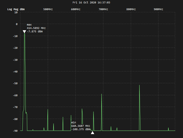
Being under the impression that the spurious emissions on Baofeng tend to be worse on the UHF band, I tried 420 MHz first. The first thing I noticed was that the fundamenal was off a bit from the where it should be. I also noticed a small forest of spurs starting at 500 MHz and extending all the way up past 800 MHz. The strongest spur was about 43 dBm down from the fundamental. The FCC rules on spurious emissions don’t seem to cover this band, but they do say that between 30 and 225 MHz, spurs need to be at least 40 dBm below the fundamental. So within the limits of my test setup, the Baofeng seems to just barely comply.
Spurious emissions from a Baofeng UV-5RA at 420 MHz. The big spur at about 825 MHz is the only one that comes close to exceeding the limits.
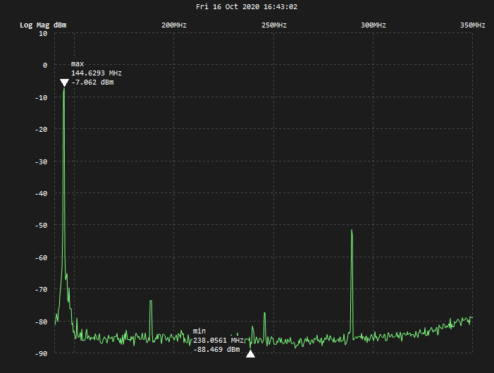
Just for completeness, I repeated the same test on the 2-m band. The signal was much cleaner here, with only a few spurs, the big one being at around 270 MHz. Again, this was about 43 dBm down from the fundamental, meaning it was probably in compliance. Again, this was only a rough test, with a test setup leaving much to be desired. But still, the tinySA is a nice way to take a look at what you’re actually putting out into the ether, and to at least get a rough idea how clean you’re operating.
A much cleaner signal from the same radio on the 2-m band.
The Not-So-Good Stuff
Like the NanoVNA before it, the tinySA has the capability of PC control. The Python program, TinySASaver, is geared mostly toward saving scans from the tinySA, but also provides additional capability, like doing frequency sweeps in segments and exporting data for further analysis. It also implements time-domain reflectometry (TDR) to measure cable lengths and find faults. Sadly, try as I might I was unable to get TinySASaver running on my Ubuntu machine. Erik is pretty clear that the code is still rough, and I’m far from a Python guru so I might be having library problems that would be easy to fix for someone with more experience. Luckily, I was able to scrounge up a decrepit Windows laptop and get a compiled version of another program running, so I didn’t have to resort to cell phone pictures for my screenshots.
I have noticed a couple of other annoying issues. The biggest is that the tinySA appears to crash when you click the screen off of one of the menus. This is annoying, as I often found myself stuck in a menu with no obvious “Back” button, and clicking on the background seemed like an intuitive way to work back to another menu. But this just throws a dump of all the registers up on the screen and locks the thing up. It’s not a huge deal to recover — toggle the power and it’ll boot right back up — but it can be annoying. I also found the touchscreen a bit finicky, which was a common complaint with the NanoVNA. The screen is far too small for my meathooks, but without a proper stylus, I resorted to a plastic spudger that worked only most of the time. Of course it was only then that I looked in the box and noticed the wrist strap with the attached guitar pick-like stylus — a thoughtful accessory indeed.
Verdict
I’m not entirely sure what I paid for the tinySA — like I said, I tend to order these things and then just forget about them. But I think it was around $60, and at that price I’d say adding a tinySA to your toolkit is a no-brainer. It’ll never substitute for a larger, full-featured instrument, but if your only need for a spectrum analyzer is to design the occasional filter or check signal quality, the tinySA is a pretty good deal.
Since the ether is an old term for the fictitious space where radio waves propagate, we always thought it was strange that the term ethernet refers to wired communication. Sure, there are wireless devices, but that’s not really ethernet. [Jacek] had the same thought, but decided to do something about it.
What he did is use two different techniques to alter the electromagnetic emission from an ethernet adapter on a Raspberry Pi. The different conditions send Morse code that you can receive at 125 MHz with a suitable receiver.
Practical? Hardly, unless you are looking to exfiltrate data from an air-gapped machine, perhaps. But it does have a certain cool factor. The first method switches the adapter between 10 Mbps and 100 Mbps. The second technique uses a stream of data to accomplish the modulation. The switching method had a range of around 100 meters while the data-based method topped out at about 30 meters. The code is on GitHub if you want to replicate the experiment.
Back in 2018, we covered [Igor’s] Easy-SDR project that aimed to provide open hardware extensions for the chap RTL-SDR receivers. If you haven’t been there for a while, it’s worth a look as there have been many recent updates. According to the author’s Reddit post:
Most of the devices are now prepared for installation in a metal case measuring 80 x 50 x 20 millimeters.
There’s a completely redesigned LNA design. Now, Bias Tee powered amplifiers are housed in a 50 x 25 x 25mm metal case and have N-type connectors.
There’s an added amplifier based on the PGA-103 microcircuit.
Added is the ability to install filters in final amplifiers (a separate printed circuit board, depending on the filter used).
A new device – SPDT antenna switch for receiving antennas.
The upconverter has been redesigned. Added intermediate buffer stage between the crystal generator and mixer.
RF lines in all devices were recalculated to correspond to the characteristic wave impedance of 50 Ohm.
Reduced size of PI attenuator PCB.
There is an emphasis on ease of assembly, so the projects generally have a gerber file and can use through hole or surface mount parts. They are also available live on EasyEDA if you want to make changes. Some of the designs, like the new upconverter, are SMD only, but for some devices these days that’s your only choice.
We were impressed with the instructions included with some of the projects. It should be very possible to duplicate these projects with just a little effort. If you missed our first pass at [Igor’s] great repo, you can still catch up. Since he uses EasyEDA, you might want to read our experience with that, too.
It wouldn’t be October without Halloween, and it wouldn’t be Halloween without some spooky music. There’s no instrument spookier than a Theremin, which also happens to be one of the world’s first electronic instruments.
Leon Theremin plays his namesake instrument. Image via Linda Hall Library
You’ve no doubt heard the eerie, otherworldly tones of the Theremin in various 1950s sci-fi films, or heard the instrument’s one-of-a-kind cousin, the Electro-Theremin in “Good Vibrations” by the Beach Boys. The Theremin turns 100 years old this month, so we thought we’d take a look at this strange instrument.
One hundred years ago, a young Russian physicist named Lev Sergeyevich Termen, better known as Leon Theremin, was trying to invent a device to measure the density of various gases. In addition to the standard analog needle readout, he wanted another way to indicate the density, so he devised an oscillator whistle that would change pitch based on the density.
He discovered by accident that having his hand in the field of the antenna changed the pitch of the whistle, too. Then he did what any of us would do — played around until he made a melody, then called everyone else in the lab over to check it out.
Theremin soon showed his device to Lenin, who loved it so much that he sent Lev on a world tour to show it off. While in New York, he played it for Rachmaninoff and Toscanini. In fact you can see a video recording of Leon playing the instrument, a performance that’s more hauntingly beautiful than spooky. In 1928, he patented the Theremin in the United States and worked with RCA to produce them.
Sales never really took off, partially because of the Great Depression, but largely because it’s so hard to get a nice sound from it. The instrument was touted as being easy to play, because you really do just wave your hands in the air to play it. But the truth is that your hands must be placed precisely to avoid terrible squawking sounds. The Theremin is quite difficult to master, and few have done it.
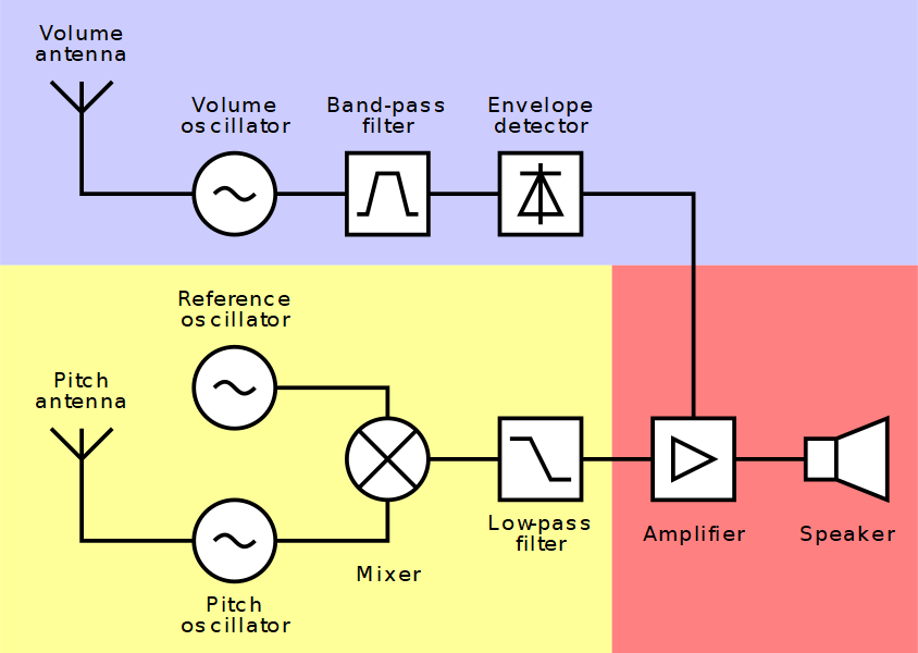
Inside the Theremin are a pair of circuits — one to control pitch, and the other to control volume. The pitch circuit uses two tuned oscillators to produce sound. One is fixed, and the other is variable and connected to a vertical antenna. Sound is produced when the player’s hand enters the electromagnetic field around the antenna. The frequency produced by the players hand is subtracted from the reference frequency of the fixed oscillator in a process called heterodyning. The difference between the two frequencies is then amplified and sent through a speaker. The volume circuit is a single oscillator connected to a horizontal loop antenna. As the player’s hand gets closer to the antenna, the volume goes down, which makes it easy to chop the sound into individual notes.
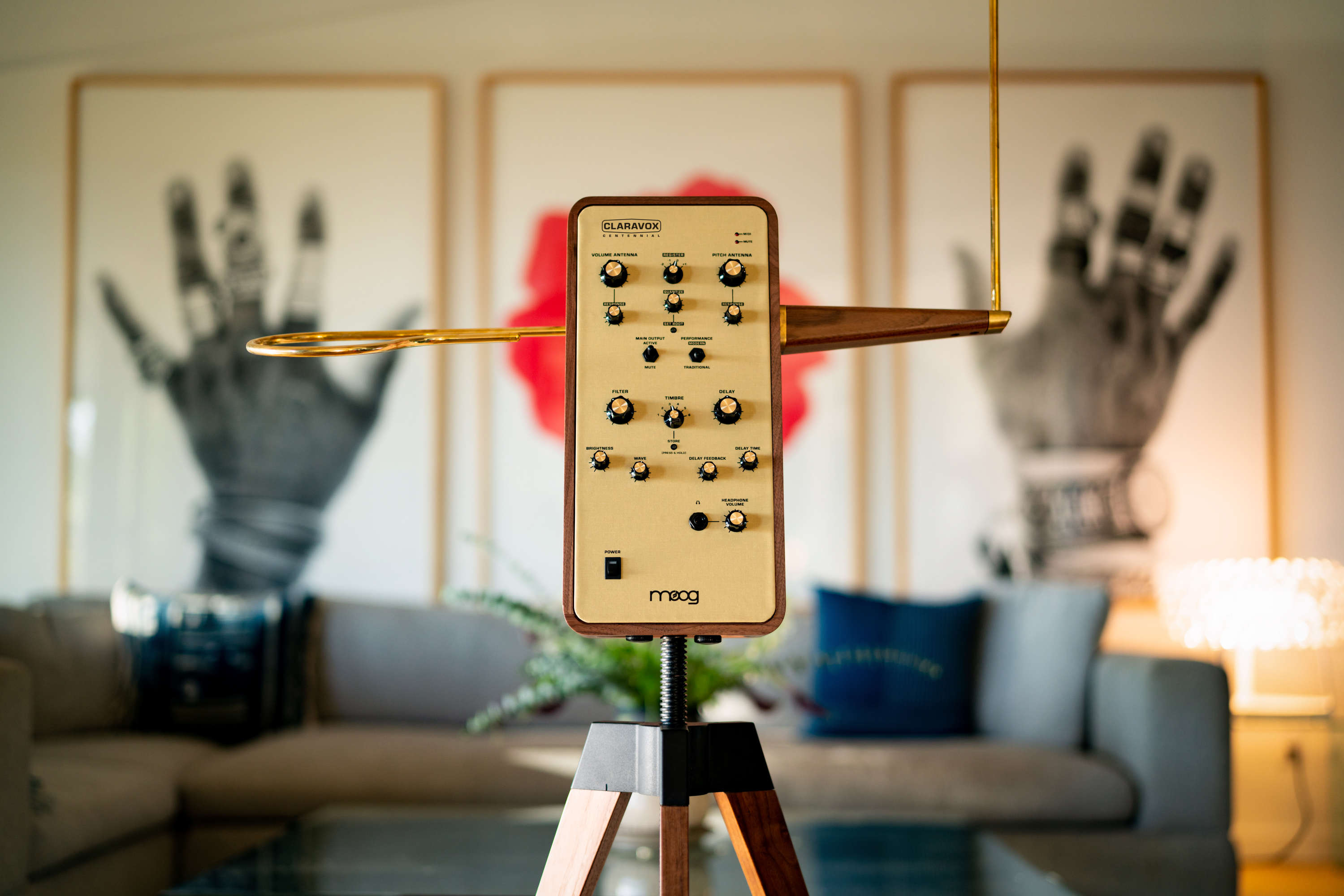
Theremins are still being made today by Moog, and many of them have more bells and whistles that make them sound more complex compared to the first Theremin, which had a sine wave sound to it. One of the best and most expressive Theremin players was Clara Rockmore, and Moog is honoring her by releasing a limited edition Theremin this month. That’s Clara in the header image.
Things didn’t work out so well for Leon Theremin. In 1938, he was kidnapped and taken back to Russia by the KGB. He spent time in a prison camp and was later forced by the government to create a bug to spy on the United States. Theremin returned to the US in 1991 at the age of 95 and gave several concerts. He died in Moscow two years later.
Leon Theremin would likely be pleased to see how many spinoffs his invention has spurred. Here’s to 100 more years of spooky, ethereal music. Take a deep dive into how the instrument works and where the art is today with this interview with Carolin Eyck.
A recent writeup by Tom Nardi about using the 6502-based NES to track satellites brought back memories of my senior project at Georgia Tech back in the early 80s. At our club station W4AQL, I had become interested in Amateur Radio satellites. It was quite a thrill to hear your signal returning from space, adjusting for Doppler as it speeds overhead, keeping the antennas pointed, all while carrying on a brief conversation with other Earth stations or copying spacecraft telemetry, usually in Morse code.
The Manual Way
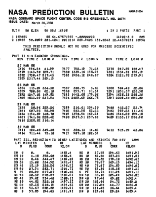
Example of NASA Prediction Bulletin, courtesy of Dr. T.S. Kelso
Pulling this off was quite a production in the pre-Internet days. To begin with, you needed data about each satellite’s orbit. This was obtained by signing up to a real-paper mailing list from NASA’s Goddard Space Flight Center. An envelope arrived about twice a week by mail containing a stack of NASA Prediction Bulletins for the satellites you had requested. These contained the orbital parameters in what’s known as two-line element (TLE) set format, which you had to then type into your computer for processing. When we communicated with Space Shuttles, we would get the preliminary and later actual TLE data from someone within NASA by phone or FAX.
Unlike geostationary communications satellites, Amateur radio satellites are typically launched in polar orbits which take between 90 to 120 minutes to complete one revolution of the Earth. To communicate through one of these satellite, first we needed to know when a particular satellite would pass over Atlanta.
To solve this problem, I wrote a Fortran program on the campus mainframe computer, a CDC Cyber 74, a real computational beast of the day. This program propagated the state vector given by the TLE data, and generated a list of orbits which passed over Atlanta. These passes were characterized by the maximum elevation, the duration of the pass, the AOS and LOS (Acquisition / Loss of Signal) times, and the distance at closest approach. We humans would filter this list even further, ignoring passes that were very short or that occurred when we would be asleep or attending class — after all, the reason we were at GA Tech was to study hard, learn a lot, and graduate with a degree.
Object                  Orbital altitude  Inclination  Orbital period
======================  ================  ===========  ==============
Oscar 8                  900 km circular  99 degrees   103 minutes
Radio Sputnik 5,6,7,8   1600 km circular  83 degrees   120 minutes
Space Shuttle STS-9      250 km circular  57 degrees    90 minutes
Space Shuttle STS-51F    315 km circular  50 degrees    91 minutes
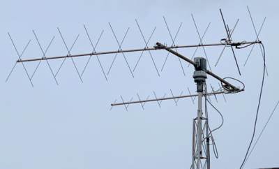
The satellites of the day had two popular modes. Mode A was easiest to use for most Hams, the uplink was in the 2 m band, and the downlink was on 10 m. Mode J also used a 2 m uplink, but the downlink was in the 70 cm band. A typical Ham satellite station would use a stationary horizontal loop antenna for 10 m reception. The 2 m and 70 cm antennas were usually Yagis, mounted on common rotatable elevation boom which was itself mounted on a vertical mast that could be rotated in azimuth. Ten meter reception was simple, no antenna movement required. Steering the Yagi antennas, however, was quite a task.
Typical steerable Yagi Antenna Array, courtesy of Gloucester County ARC, W2MMD
Having selected a suitable orbit, next we had make those Yagis follow the path of the satellite. In Amateur satellite stations, this is a completely open-loop process. You calculate where the satellite will be at a certain time, and drive the antennas to that point in space. If you remember the old home steerable TV antennas, before cable TV and streaming, the arrangement in a Ham shack is very similar. There is a rotator control box for each rotor, with an analog meter indicating direction, modern ones being digital, of course. These control boxes usually had three buttons for steering: Left, Right, and Brake release.
To follow the satellite, we had a couple of techniques available. One method used a graphical overlay of the satellite’s ground track and footprint on top of a polar projection map of the Earth. By rotating the ground track overlay to match the orbit’s position as given by the orbital parameter with the coolest name, Right Ascension of the Ascending Node, we could visually see the satellite’s path over our station. The ground path overlay has time tick marks, and the footprint overlay has azimuth lines and elevation rings. This crude graphical technique provides the basic information needed to track the satellite, within the broad beamwidth of our antennas. We also had to keep our clocks synchonized to WWV or WWVH — no Network Time Protocol back then.
Oscarlocator from the author’s personal collection.
A second technique was more precise, but required a trip across campus. Using another Fortran program, I could print a table of time, azimuth and elevation angles for a desired orbit. The operator wouldn’t have to interpolate angles from the graphical overlays: the numbers are clearly shown on the computer printout paper. Getting this data from the campus computer wasn’t trivial, however. Usually I would visit the computer center building across campus, login to my account at a terminal, and type in the data by hand. Upon execution, the program would generate a printout.
Then I had to wait at the output counter for the operator to separate and distribute the printouts to all of us impatient users. We felt so lucky when the club obtained a portable printing terminal with a built-in acoustic modem. This meant we could dial into the mainframe and run the programs remotely, and get our orbit schedules and tracking tables immediately without crossing campus — at the blazingly fast speed of 300 baud!
While all these machinactions were certainly within our grasp, it took quite a bit of effort and advance planning. And while a lone operator could communicate with a satellite, two people were better — one to operate the radios, the other to steer the antennas. I recall two events from this period which led me to consider a computer controlled project. First of all, we inherited two Commodore PET computers from one of the EE professors. Secondly, we had an ongoing issue controlling equipment up on the roof of the 5th floor from our shack located at basement level. There just weren’t enough wires to do all the things we wanted even for normal HF operations, much less satellite tracking.
Commodore PET to the Rescue
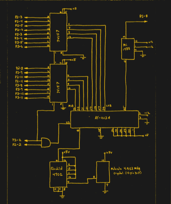
The Commodore PET computers we had were modified from their standard factory condition. They had full-size external keyboards, so you didn’t have to use the Chiclet keys. The internal memory had been upgraded to 32K RAM. My report from 1983 says this expansion memory card also had two general purpose 8-bit TTL output registers, which were used to talk to the outside world.
As shown in this diagram, the PET computer talks to two devices — the Rotor Control Interface selects and operates the rotor boxes, and the Digital Serial Transmitter, essentially just a UART that sent data serially to the roof to remotely control a variety of equipment. Rotor control was fun, because we only had one rotor control cable between the shack the the roof. I had to implement 8P3T switches out of relays and multiplexed the cable between rotors. This means that only one rotor could rotate at a time, but this wasn’t a severe constraint for our purpose.
Besides the rotator control signal multiplexing, there was quite a bit of auxilliary equipment on the roof which had to be remotely controlled. As shown in the diagram, we had RF coaxial relays to switch VHF/UHF antenna polarization, and to switch between 10 m and 70 cm downlink signal paths. In addition, there were preamps, down-converters, and power amplifiers which had to be turned on and off. Except for rotor multiplexing, most of these were static setups for the duration of a satellite pass, although the PET had full control of everything over this interface. We made a UART interface connected to one of the PET’s TTL output registers to send this control data serially to the roof for control. I hand-drew all the schematics and hand-taped the PCB artwork – no KiCad back then.
I very quickly identified a problem having the PET control of all this rooftop gear, which was not related to satellite operations at all. The PET wasn’t running 24/7, and it was slow to boot and load up from cassette tape. Operators who just needed to control relays on the roof for HF operations didn’t want to wait 10+ minutes to boot the PET. In fact they were quite vocal about it. So I added a manual control panel to bypass the PET. This philosophy has served me well over the years — computer control is great, but there are times when you need manual control, if only for testing.
We Don’t Need Closed Loops
There was still one problem with this setup — you might have noticed there is no feedback. There was a method for the PET to read signals, but despite trying a variety of methods we couldn’t get a stable enough feedback within our limited budget and limited mechanical skills. The azimuth rotor, which had an integrated feedback signal, would have been the easiest to monitor. But the elevation rotor we used didn’t have any such feedback.
We tried a long rod with a lead weight at the bottom, attached to a potentiometer. When the boom rotated up and down in elevation, the rod always pointed down. Good idea on paper, didn’t work so well in practice. We briefly played with synchromotors, which were really cool. Turn the shaft of one motor and the other motor across the room also turned the same amount, connected only by a few wires. But even these few wires were too many for our peculiar installation.
In the end, I concluded that for the satellites of interest and the antenna beamwidths involved, running the antenna rotation controls open loop was workable. To be sure, it caused a lot of headaches to procedurally check alighment before a pass, but once the pass began it worked as desired. I was continually tweaking the computer model of the antenna rotation, both the mathematical model and the constants such as dead-time, rotation speed, acceleration, etc. It was a crude solution, but it got the job done within our limited budget.
Aside: Zenith crossing and three axis mounts
You might think that a satellite passing directly overhead would be perfect — it is as close as possible to your station. Well, that’s not necessarily good. The problem is that when the satellite passes overhead, and the elevation angle approaches 90 degrees, the azimuth rotor will suddenly have to spin at an incredibly fast rate to keep pointed. There are ways to mitigate this — one method is to accept some pointing error and steer the antenna in a small circle around zenith — a circle whose diameter is determined by the speed of the satellite and the maximum speed of your rotor.
A more elegant solution, but mechanically complex, is to add a third axis of rotation. Two of the rotors are positioned before the satellite pass so that the antenna boom connected to the third rotor is perpendicular to the orbital plane. This way, only the third rotor is used during the satellite pass, and the other two rotors remain fixed.
Where is OSCAR?
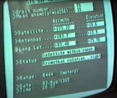
Providing the PET with interfaces to the real world was only half the battle. I still needed a way to calculate the satellite’s position. And while it was great to have a computer in the shack, the PET computer was thousands of times less powerful than the campus mainframe. There was no GUI, no tracking map of the Earth, just updating data fields on a text-based status screen.
Satellite Tracking Screen, courtesy of Sherman Banks.
I remember one major issue in the software development, however. There were several programs floating around the community those days for tracking satellites, and I hand typed one of the popular ones into the PET. I contacted the author of this program to let him know about my school project and get his permission.
But to my surprise, he replied “No, you can’t use my software”. Just a minor setback for a young college student who doesn’t know his limitations — I went to the GA Tech library, checked out a couple of books on orbital mechanics, and wrote my own algorithms. Surprisingly, the fundamental Keplerian laws and equations for orbital bodies aren’t that difficult to understand and calculate. Alas, when you solve for the antenna pointing angles to the satellite, it results in a transcendental equation. Solving that on the mainframe took milliseconds, but it painfully slow on the PET. Over a month or so that followed, I confined myself to programming at home all weekend, developed an life-long addiction to caffeine-laden diet colas, and emerged with a working program.
Upgrades
The manual controls for rooftop equipment were non-intuitive. You were literally toggling address and data bits into a UART. This could have been improved, of course, but a few of us began to question the original “no more wires can be routed to the roof” constraint. It turns out that it was indeed possible, with a bit of effort. A larger cable for signaling was pulled to the roof, and an improved interface panel was made. Furthermore, the PET was showing its age, too, so we upgraded to the Commodore C64 — with floppy disk storage. I made a new, smaller rotor control interface that connected to the C64’s user port and controlled the rotors by relays.
Successful Ops
The system, while a bit finicky, did serve us well for a few years. Not only were we able to communicate over Amateur Radio satellites, but quite proudly we contacted the first two astronauts allowed to operate from the Space Shuttle under a new program called SAREX. In Nov 1983 Dr. Owen Garriott (W5LFL) heard us on Columbia’s STS-9 mission, which was piloted by our own GA Tech alumni Dr John Young. We were also proud of our own recent club alumni, Jim Worsham, W4KXY, who was on the team at Motorola that designed and built the custom radio used by Dr. Garriott.
QSL Card from Owen Garriott W5LFL, courtesy of Sherman Banks.
Again in Aug 1985, we contacted Dr Tony England (W0ORE) on Challenger’s STS-51F Spacelab mission. Videos were made of these efforts, which you can see in the links below.
I challenged myself last year to build a miniature version of this project that fits in an Altoids can. It’s on the back burner for now, until I can track down a copy of the original software. Stay tuned…
Wrapping Up
After couple of years after I graduated, the company I worked with generously let me manufacture and market this C64-based tracking system under the unimaginitive name Satellite AutoTracker. That’s a story for another day.
I can’t overemphasize the impact this project had on me. The act of conversing with another radio station via a satellite pulls together so many engineering and science disciplines, from the physics of orbits and Doppler shifts to the minute details of learning to build PCBs to the overall system engineering efforts to make it all play together. Each one of these were interesting in and of themselves, but it was just plain awesome when it all successfully meshed together and worked.
I learned a lot building this project, but it didn’t seem like learning because it was so fun. That, folks, is the best way to learn.
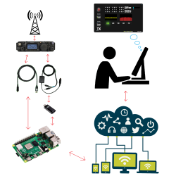
It’s a common scene: a dedicated radio amateur wakes up early in the morning, ambles over to their shack, and sits in the glow of vacuum tubes as they call CQ DX, trying to contact hams in time zones across the world. It’s also a common scene for the same ham to sit in the comfort of their living room, sipping hot chocolate and remote-controlling their rig from a laptop. As you can imagine, this essentially involves a server running on a computer hooked up to the radio, which is connected via the internet to a client running on the laptop. [Olivier/ F4HTB] saw a way to improve the process by eliminating the client software and controlling the rig from a web browser.
[Oliver]’s software, aptly named Universal HamRadio Remote, runs a web server that hosts an HTML5 dashboard for controlling the radio. It also pipes audio back and forth (radio control wouldn’t be very useful if you couldn’t talk!), and can be run on a Raspberry Pi. Not only does this make setup easier, as there is no need to configure the client machine, but it also makes the radio accessible from nearly any modern device.
We’ve seen a similar (albeit expensive and closed-source) solution, the MFJ-1234, before, but it’s always refreshing to see the open-source community tackle a problem and make it their own. We can’t wait to see where the project goes next!
Software-defined radio came on the hacker scene in a big way less than a decade ago thanks to the discovery that a small USB-based TV tuner dongle could be used for receiving all kinds of radio transmissions. Two popular projects from that era are tracking nearby airplanes and boats in real time. Of course, these projects rely on different frequencies and protocols, but if you live in a major port city like [Ian] then his project that combines both into a single user interface might be of interest.
This project uses an RTL-SDR dongle for the marine traffic portion of the project, but steps up to a FlightAware Pro dongle for receiving telemetry from airplanes. Two separate antennas are needed for this, and all of the information is gathered and handled by a pair of Raspberry Pis. The Pis communicate with various marine and air traffic databases as well as handles the custom user interface that knits both sets of information together. This interface was custom-built from a previous project of his and was repurposed slightly to fit the needs of this one.
This is a great project that goes into a lot of interesting detail about how the web traffic moves and how the UI works, so even if you’re not into software-defined radio it might be worth a look. However, it’s also worth noting that it hasn’t been easier to set up a system like this thanks to the abundance and low price of RTL-SDR dongles and the software tools that make setting them up a breeze.
Ham radio operators love to push the boundaries of their equipment. A new ham may start out by making a local contact three miles away on the 2m band, then talk to somebody a few hundred miles away on 20m. Before long, they may find themselves chatting to fellow operators 12,000 miles away on 160m. Some of the adventurous return to 2m and try to carry out long-distance conversations by bouncing signals off of the Moon, waiting for the signal to travel 480,000 miles before returning to Earth. And then some take it several steps further when they listen to signals from spacecraft 9.4 million miles away.
That’s exactly what [David Prutchi] set out to do when he started building a system to listen to the Deep Space Network (DSN) last year. The DSN is NASA’s worldwide antenna system, designed to relay signals to and from spacecraft that have strayed far from home. The system communicates with tons of inanimate explorers Earth has sent out over the years, including Voyager 1 & 2, Juno, and the Mars Reconnaissance Orbiter. Because the craft are transmitting weak signals over a great distance (Voyager 1 is 14 billion miles away!), the earth-based antennas need to be big. Real big. Each of the DSN’s three international facilities houses several massive dishes designed to capture these whispers from beyond the atmosphere — and yet, [David] was able to receive signals in his back yard.
Sporting a stunning X-band antenna array, a whole bunch of feedlines, and some tracking software, he’s managed to eavesdrop on a handful of spacecraft phoning home via the DSN. He heard the first, Bepi-Colombo, in May 2020, and has only improved his system since then. Next up, he hopes to find Juno, and decode the signals he receives to actually look at the data that’s being sent back from space.
We’ve seen a small group of enthusiasts listen in on the DSN before, but [David]’s excellent documentation should provide a fantastic starting point for anybody else interested in doing some interstellar snooping.
What do you do with an old cable modem in a closet? If you are [stdw] you reverse engineer it and turn it into a software-defined radio. The modem in question was a Motorola MB7220. After looking at a similar project using a different modem, it seemed like it should be doable.
Cracking open the case revealed two likely UART ports, one of which was active. The output from that UART provided a lot of info. The chip was a Broadcom BCM3383 which is a MIPS processor. It had eCos as an operating system. However, the bootloader eventually disables the UART, so there wasn’t much more investigation possible via the serial terminal.
The next step was to dump the flash memory. That required a little solder surgery to prevent the board from starting while the flash chip had power. It appeared that some key credentials and configuration data were present, but they were really backups. After doing a factory reset to remove the backups, the right data was apparent.
After some lengthy exploration, the diagnostic that builds a spectrum display gave up its data. At first, the data was just a small sample of what was really required, but it did show a local FM station as a spectrum. Eventually, the data loss rate was down to about 12% when streaming which is not great, but good enough. You can hear an audio clip of the reception. Not exactly crystal-clear quality, but not bad.
Of course, no one will use this for an FM radio. But it is a fascinating view into how far you can hack into a device like this if you have some skills and patience. There must be something about quarantine that is making people hack old gear, as we just recently saw a similar Netgear hack. Even cheap games aren’t safe.
WiFi is an ubiquitous feature of the modern landscape, but due to power restrictions on most hardware alongside the high-frequency signal it’s typically fairly limited in range. This of course leads to frustration where a WiFi signal can be seen, but the connection is unreliable or slow. While most would reach for a range extender or other hardware bridge, [tak786] was able to roll out a better solution for his workplace by using a high-gain antenna and a single-board computer which gets him an amazing kilometer-wide WiFi network.
The build uses a 10 dBi antenna from TP-Link that’s rated for outdoor use and a single-board computer which acts as a sort of router. The antenna is placed at the top of a building which certainly helps with the extreme range as well. This setup doesn’t actually broadcast an open Internet connection, though. [tak786]’s employer needed a teleconferencing solution for their building, and he also created a fully open-source video conferencing solution called trango that can run on any LAN and doesn’t require an Internet connection. The WiFi setup in this build is effectively just a bonus to make the conferencing system more effective.
While M17 might sound like a new kind of automatic rifle (as actually, it is), we were referring to an open source project to create a ham radio transceiver. Instead of paraphrasing the project’s goals, we’ll simply quote them:
The goal here should be to kick the proprietary protocols off the airwaves, replace DMR, Fusion, D-Star, etc. To do that, it’s not just good enough to be open, it has to be legitimately competitive.
Like some other commercial protocols, M17 uses 4FSK along with error correction. The protocol allows for encryption, streaming, and the encoding of callsigns in messages. There are also provisions for framing IP packets to carry data. The protocol can handle voice and data in a point-to-point or broadcast topology.
On the hardware side, the TR-9 is a UHF handheld that can do FM voice or M17 with up to 3 watts out. The RF portion uses an ADF7021 chip which is specifically made to do 4FSK. There’s also an Arm CPU to handle the digital work.
We were struck by the similarity of the TR-9 to a cell phone since it has an LCD display, an SD card slot, and a 9DOF sensor. Maybe some open hardware cell phones and open hardware ham radios could find common ground.
This is quite ambitious, but generally, small ham rigs are having a resurgence. Having high-quality RF components available as chips makes a lot of difference.
Once you move away from the usual software defined radio (SDR) dongles, you have only a few choices unless you want to drop some serious cash. One common hobby-grade SDR is the KiwiSDR. This popular unit runs Linux and can receive up to 30 MHz. The platform uses a dedicated A/D converter, an FPGA, and BeagleBone computer. Success of course breeds imitators, and especially when you have an open source design like the Kiwi, you are going to find similar devices with possibly different end goals. That’s how the RaspberrySDR came to be. This is a very similar unit to the KiwiSDR but it uses a Raspberry Pi, along with a handful of other differences. What’s different? [KA7OEI] tells us in a recent blog post.
Other than the obvious difference of the computer and all that it entails, the RaspberrySDR has a higher speed A/D (125 MHz vs 66 MHz) and 16-bits of resolution instead of the Kiwi’s 14 bits. This combines to give the Raspberry a wider receive range (up to 60 MHz) and — in theory — better performance in terms of dynamic range and distortion.
[KA7OEI] measures a few key parameters on both devices and arrived at some surprising conclusions. The Kiwi appears to boost signals near its cutoff frequency to compensate for losses in the system. The Raspberry — using adapted software — looks as though it does the same trick, but does it around the Kiwi’s cutoff frequency, which is lower. Probably a software fix could take care of that, of course.
There are also tests of image rejection and front-end overloading. The tests revealed a few problems with signal strength measurement and some other problems with the RaspberrySDR. The biggest issue, though, was that the 16-bit A/D didn’t seem to have better performance. Without proper design, throwing more bits at a problem isn’t always helpful and this appears to be a good example of that.
In the end, the Raspberry looks like a cheap clone of the Kiwi with some benefits, but also some drawbacks. The blog post also covers some open source issues where Kiwi is now saying some parts of their code will only be binary in the future and there has been some difficulty finding all of the Raspberry’s files. If you are looking to buy one, you might not find the name “raspberrysdr” but [KA7OEI] suggests searching for “New 16bit 62M real-time bandwidth network shared SDR receiver” which does turn up some results.
Amateur radio operators and shortwave listeners have a common enemy: QRM, which is ham-speak for radio frequency interference caused by man-made sources. Indiscriminate, often broadband in nature, and annoying as hell, QRM spews forth from all kinds of sources, and can be difficult to locate and fix.
But [Emilio Ruiz], an operator from Mexico, got a little help from Mother Nature recently in his quest to lower his noise floor. Having suffered from a really annoying blast of RFI across wide swaths of the radio spectrum for months, a summer thunderstorm delivered a blessing in disguise: a power outage. Hooking his rig up to a battery — all good operators are ready to switch to battery power at a moment’s notice — he was greeted by blessed relief from all that noise. Whatever had caused the problem was obviously now offline.
Rather than waste the quiet time on searching down the culprit, [Emilio] worked the bands until the power returned, and with it the noise. He killed the main breaker in the house and found that the noise abated, leading him on a search of the premises with a portable shortwave receiver. The culprit? Unsurprisingly, it was a cheap laptop power supply. [Emilio] found that the switch-mode brick was spewing RFI over a 200-meter radius; a dissection revealed that the “ferrite beads” intended to suppress RFI emissions were in fact just molded plastic fakes, and that the cord they supposedly protected was completely unshielded.
We applaud [Emilio]’s sleuthing for the inspiration it gives to hunt down our own noise-floor raising sources. It kind of reminds us of a similar effort by [Josh (KI6NAZ)] a while back.
Electronic devices can be surprisingly leaky, often spraying out information for anyone close by to receive. [Docter Cube] has found another such leak, this time with the speakers in iPhones. While repairing an old AM radio and listening to a podcast on his iPhone, he discovered that the radio was receiving audio the from his iPhone when tuned to 950-970kHz.
[Docter Cube] states that he was able to receive the audio signal up to 20 feet away. A number of people responded to the tweet with video and test results from different phones. It appears that iPhones 7 to 10 are affected, and there is at least one report for a Motorola Android phone. The amplifier circuit of the speaker appears to be the most likely culprit, with some reports saying that the volume setting had a big impact. With the short range the security risk should be minor, although we would be interested to see the results of testing with higher gain antennas. It is also likely that the emission levels still fall within FCC Part 15 limits.
I've confirmed this on an 8 non-pro AND discovered that when you're around 960 KHz you ALSO can detect the haptic clicks! I am suspecting that they are running a class D amp with the PWM at 960 KHz, which would be 20x 48khz-right on the mark for a class D amp. Video demo of both. pic.twitter.com/EbodZS11kB
The phenomenon of electronics leaking unintended information in magnetic waves has been knows since WW2, and it even has a codename, TEMPEST. If you want to learn more about it and do some experimentation, there are a number of open source software toolkits you can play with.
[8BitsAndAByte] are back and this time they’re using AI to create an interactive storyteller. With the help of a Raspberry Pi, they upcycled an old Cold War era radio they dug up and the results are pretty impressive.
The main controller board of the radio was intact, so it was easy to use all the preexisting hardware to control the speaker and to trigger a few of the Pi’s GPIO using the buttons and switches on the radio’s front panel. To add some artificial intelligence, they used Google’s AIY Voice Kit, allowing them to tap into Google’s seemingly endless artificial intelligence platform. This could be a “tables have turned moment,” but we’re probably being a bit too hopeful.
Anyway, they used a pretty interesting piece of software called Dialogflow that creates a somewhat natural conversational interaction akin to a chatbox. Dialogflow processes speech to text, as you would expect, but can also interpret contextual speech and provide contextual responses. Pretty neat…but maybe also a little creepy. Who knows? The jury is still out.
There is a long history of spacecraft carrying ham radio gear, as the Space Shuttle, Mir, and the ISS have all had hams aboard with gear capable of talking to the Earth. However, this month, the ISS started operating an FM repeater that isn’t too dissimilar from a terrestrial repeater. You can see [TechMinds] video on the repeater, below.
The repeater has a 2 meter uplink and a 70 centimeter downlink. While you can use a garden variety dual-band ham transceiver to use the repeater, you’ll probably need a special antenna along with special operating techniques.
One of the problems you’ll find is that ISS moves fast enough that you will observe doppler shift in the frequencies. The video reproduces a table of frequencies you may have to move through to receive the shifting signal.
You can probably hear the ISS with a good pass with no special equipment, but [TechMinds] wasn’t able to close an actual contact in the video. But [K0LWC] got really close using a pretty standard radio setup, as you can see in the second video.
The ISS has been on the air with digital repeaters and conventional FM radio for some time. The antenna you need doesn’t have to be a huge disk. We’ve seen it done with a handheld beam antenna and a handheld radio.
Ever wonder what was inside a cell phone booster, or what it is like to set up or use one? If so, [Kerry Wong]’s got you covered with his teardown of a Cel-Fi Go X Cell Signal Booster by Nextivity. [Kerry] isn’t just ripping apart a cheap unit for laughs; his house has very poor reception and this unit was a carefully-researched, genuine investment in better 4G connectivity.
The whole setup consists of three different pieces: the amplifier unit pictured above, and two antennas. One is an omnidirectional dome antenna for indoors, and the other is a directional log-periodic dipole array (LPDA) antenna for outdoors. Mobile phones connect to the indoor antenna, and the outdoor antenna connects to the distant cell tower. The amplifier unit uses a Bluetooth connection and an app on the mobile phone to manage settings and actively monitor the device, which works well but bizarrely doesn’t seem to employ any kind of password protection or access control whatsoever.
Overall [Kerry] is happy, and reports that his mobile phone enjoys a solid connection throughout his house, something that was simply not possible before. Watch a hands-on of the teardown along with a short demonstration in the video embedded below.
Devices that claim to enhance or boost wireless signals of various kinds seem to attract more than their share of snake oil salesmen, but [Kerry]’s teardown reminds us there are legit hardware offerings (albeit ones with imperfect management app design.) There is also junk out there, like this antenna that was outperformed by a literal rusty nail.
There was a time when a ham radio set up sported many dials and switches and probably quite a few boxes as well. Computers have changed all that. Some transceivers now have just a few buttons or are even totally computer-controlled. Where a ham, at one time, might have a TeleType machine, a slow-scan TV monitor, and a fax printer for receiving satellite images, now that can all be on a single computer which can even be a Raspberry Pi. [F4GOH] has a post that takes you from the fundamentals to installing everything from an SDR to many common ham programs for digital modes, APRS, SSTV, and more. You can download the seven-part tutorial as separate PDF files, too.
Even if you aren’t a ham, you might find some of the software interesting. OpenWebRX lets you listen to your software defined radio on the road. You can use other software to pick up weather satellite data.
If you are a seasoned Linux user, you won’t need some of the early material. But you will find some good notes on how to use the ham-specific software and get a good overview of what is possible.
Ham radio has changed a great deal. If you think of it as people with noisy large radios, you might be surprised. The hobby is big enough that you’ll find everything from people talking on tiny radios around the world using a hybrid of radio and Internet connectivity, to people bouncing signals off the moon or using ham radio satellites.
[Dan Maloney] has talked about how to get started in ham radio for under $50. Then again, you might need another $50 for the Raspberry Pi. Of course, there are plenty of opportunities to hack the gear.
If you spend enough time trolling eBay for interesting electronic devices to take apart, you’re bound to start seeing suggestions for some questionable gadgets. Which is how I recently became aware of these tiny GPS jammers that plug directly into an automotive 12 V outlet. Shipped to your door for under $10 USD, it seemed like a perfect device to rip open in the name of science.
Now, you might be wondering what legitimate uses such a device might have. Well, as far as I’m aware, there aren’t any. The only reason you’d want to jam GPS signals in and around a vehicle is if you’re trying to get away with something you shouldn’t be doing. Maybe you’re out driving a tracked company car and want to enjoy a quick two hour nap in a parking lot, or perhaps you’re looking to disable the integrated GPS on the car you just stole long enough for you to take it to the chop shop. You know, as one does.
But we won’t dwell on the potentially nefarious reasons that this device exists. Hackers have never been too choosy about the devices they investigate and experiment with, and there’s no reason we should start now. Instead, let’s take this piece of gray-area hardware for a test drive and see what makes it tick.
Can You Hear Me Now?
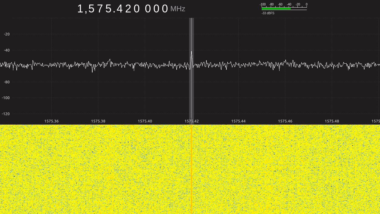
While the GPS constellation average altitude of 20,200 km (12,550 miles) might not be quite as high up as communication satellites in geosynchronous orbit, they’re still pretty far away. With this incredible distance in mind, and given the size of the antenna on most GPS-equipped devices, it’s no wonder that the received signal is very weak. So weak, in fact, that it’s generally below the noise floor. Only with clever algorithms and a dash of wizardry can your phone turn this whisper from the stars into anything resembling useful information.
When viewed by an RTL-SDR, the GPS signal is like a needle in a haystack.
It’s this fragility that makes these sort of low-cost jammers possible. It doesn’t take much to overpower the legitimate signal. Keep in mind that a device like this isn’t trying to mimic a GPS satellite, it’s simply broadcasting out enough loud nonsense that the real satellite can no longer be heard.
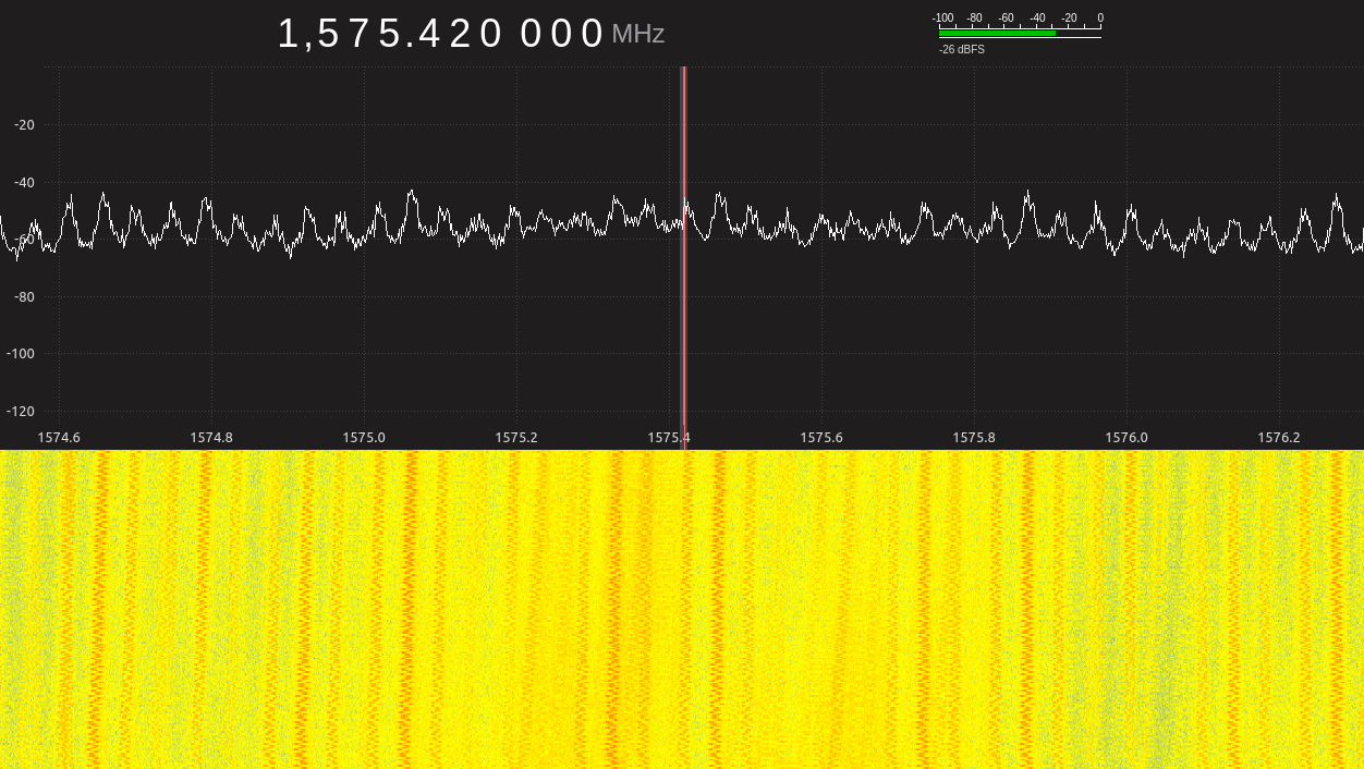
With the jammer powered up, we can clearly see how the already meager signal is absolutely obliterated by the patterns being broadcast by the device.
With the jammer switched on, the signal becomes a needle in a haystack of needles.
There’s simply no contest; the legitimate signal is tens of thousands of kilometers away, and this thing is screaming its head off at arm’s reach. I didn’t test the range of this device, mainly because I didn’t want to have it powered up for any longer than necessary, but it’s certainly capable of doing the deed at several meters at least.
Betrayed By an Old Friend
Now that we’ve broken federal law for a few minutes by operating this device (seriously, don’t buy one of these) and verified that the dastardly thing does what it’s advertised to do, the only thing left to do is open it up and figure out how it works. For the $8 I paid for this unit I certainly wasn’t expecting a lot inside, but even still, it’s fascinating to see just how easy it is to cause so much trouble.
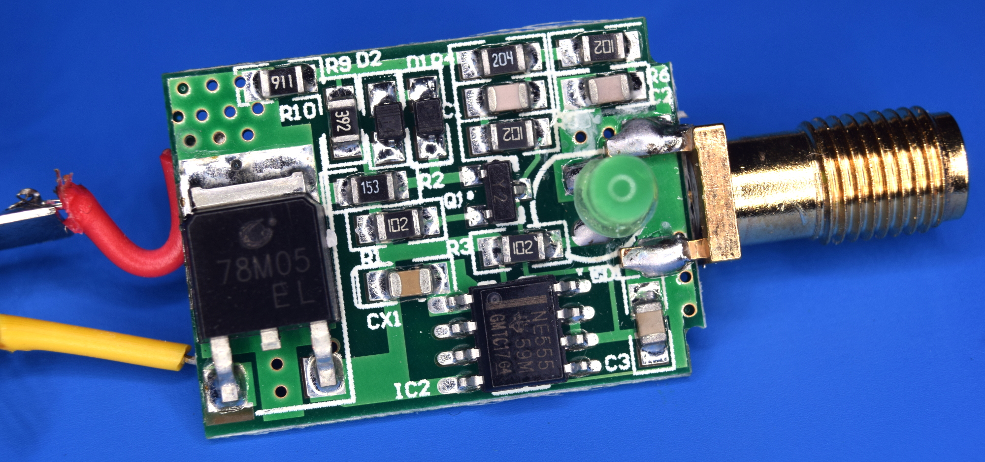
After years of losing work to the Arduino, the 555 timer has fallen in with the wrong crowd.
On one side of the PCB we can see there are only two major components, a 78M05 regulator to step the vehicle’s 12 volts down to 5 volts, and the hacker’s old friend, the NE555 timer. It’s a shame to see that it takes a teardown of an illegal jammer before we see one of the most iconic ICs in the history of electronics, but there you have it.
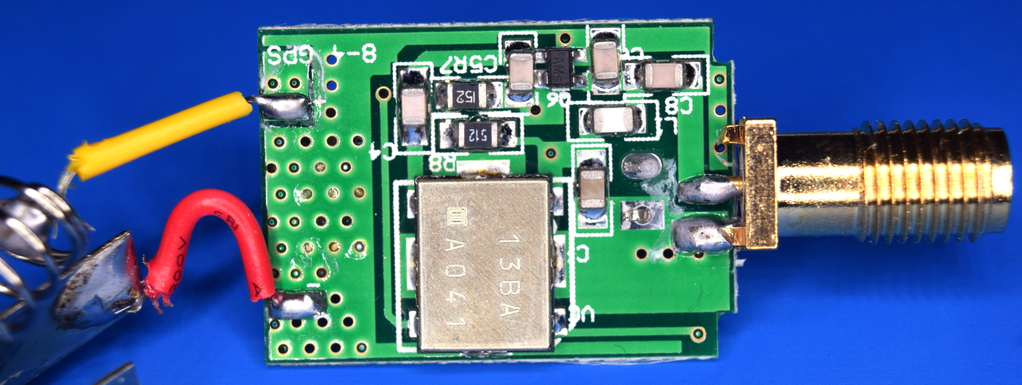
Still, unless you’re looking to jam an AM radio, a 555 isn’t going to cut it. Flipping the board over, we get our first glance at the real trouble maker.
RF Witchcraft in a Can
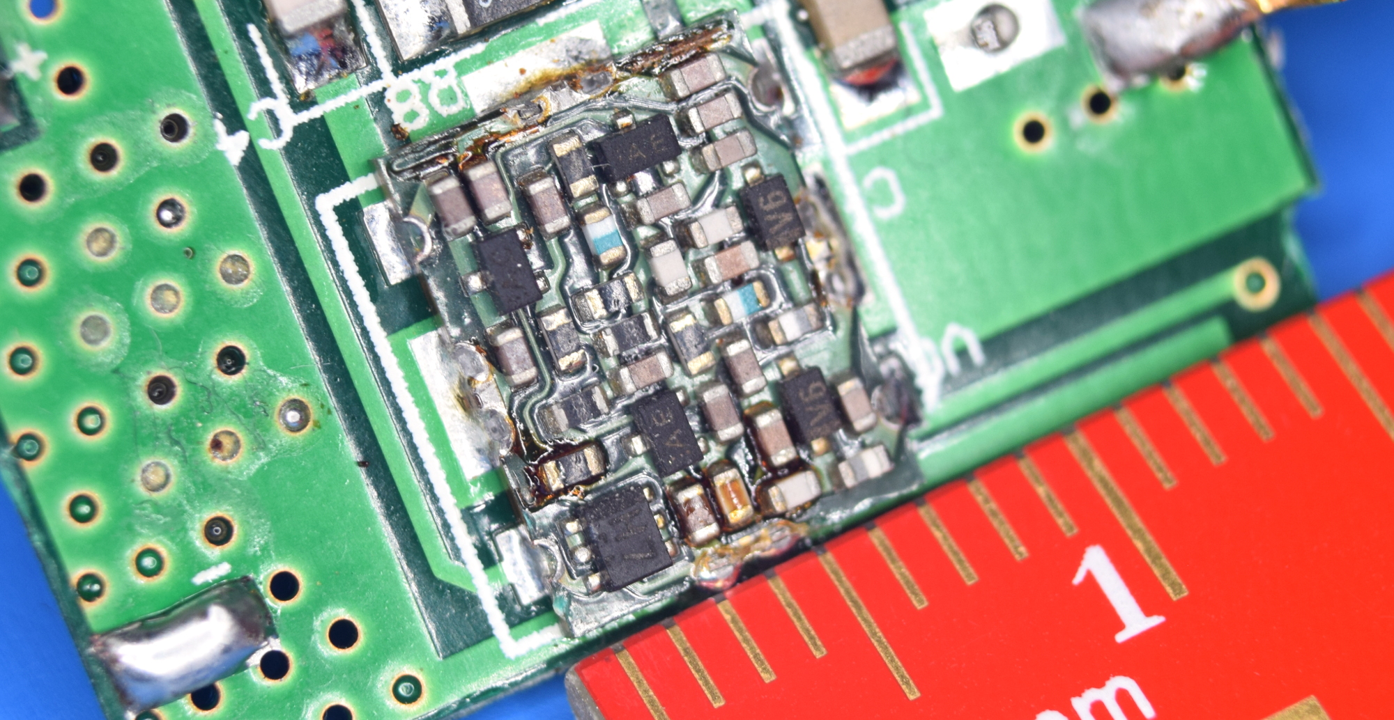
Clearly this component, labeled 13BA A041, is the star of the show. But what is it? While I wasn’t able to find a datasheet for this specific model, what we’re looking at is a microwave voltage-controlled oscillator (VCO). The visible top plate is actually a metallic shield, and with a bit of persuasion, we can look inside to see the incredible array of components that have been packed into the 9 mm x 7 mm area.
The basic theory of operation here is that the VCO’s control pin (labeled VC on the silkscreen) is connected to the output of the 555 timer on the other side of the board. The signal coming from the 555 modulates the output of the VCO, causing the noise we see centered on the 1,575 MHz GPS frequency.
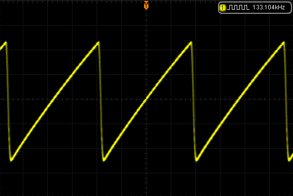
With the scope connected to the VC pin, we can see the 133 KHz sawtooth signal being produced by the 555 timer. If you were to adjust this signal you could potentially shift around the frequency range that the jammer operates on, though without a datasheet for the VCO, it’s difficult to say how far you could push it in either direction. But since these were presumably the cheapest components available, probably not very far.
It’s also worth taking a close look at the small four pin device at the top of the board labeled Q6. Located directly in the path of the high frequency signal as it passes from the VCO to the center pin of the antenna connector, this would be a logical place to put an amplifier. Though it may also be some kind of a diode to protect the electronics from anything that’s picked up from the antenna.
An Unfortunate Surprise
Part of me assumed that the Mini GPS Jammer just wouldn’t work, or at least, it would work so poorly as to not be an issue. But no, in a break from tradition, a cheap imported device from eBay managed to actually exceed all of my expectations.
Not that I’m happy about it. Sure the information to build a jammer like this has been out in the wild for years, but you still needed to have the wherewithal to actually source the parts and assemble it. With such a low bar for entry, this device is clearly quite dangerous in the wrong hands. While a WiFi or cellular jammer would perhaps present a more immediate threat, this is still not technology that anyone wants to see proliferate.





 remote-controlling their rig from a laptop. As you can imagine, this essentially involves a server running on a computer hooked up to the radio, which is connected via the internet to a client running on the laptop. [Olivier/ F4HTB] saw a way to improve the process by eliminating the client software and controlling the rig from a web browser.