Saturday, August 31, 2019

A Radio Transceiver From A Cable Modem Chipset

It’s a staple of our community’s work, to make electronic devices do things their manufacturers never intended for them. Analogue synthesisers using CMOS logic chips for example, or microcontrollers that bitbang Ethernet packets without MAC hardware. One of the most fascinating corners of this field comes in the form of software defined radios (SDRs), with few of us not owning an RTL2832-based digital TV receiver repurposed as an SDR receiver.

The RTL SDR is not the only such example though, for there is an entire class of cable modem chipsets that contain the essential SDR building blocks. The Hermes-Lite is an HF amateur radio transceiver project that uses an AD9866 cable modem chip as the signal end for its 12-bit SDR transceiver hardware with an FPGA between it and an Ethernet interface. It covers frequencies from 0 to 38.4 MHz, has 384 kHz of bandwidth, and can muster up 5W of output power.

It’s a project that’s been on our radar for the past few years, though somewhat surprisingly this is the first mention of it here on Hackaday. Creator [Steve Haynal] has reminded us that version 2 is now a mature project on its 9th iteration, and says that over 100 “Hermes-Lite 2.0” units have been assembled to date. If you’d like a Hermes-Lite of your own it’s entirely open-source, and they organise group buys of the required components.

Of course, SDRs made from unexpected components don’t have to be exotic.


via Radio Hacks – Hackaday https://ift.tt/2Ump1qM
Friday, August 30, 2019

Steampunk Radio Looks The Business

Radios are, by and large, not powered by steam. One could make the argument that much of our municipal electricity supply does come via steam turbines, but that might be drawing a long bow. Regardless, steampunk remains a popular and attractive aesthetic, and it’s the one that [Christine] selected for her radio build.

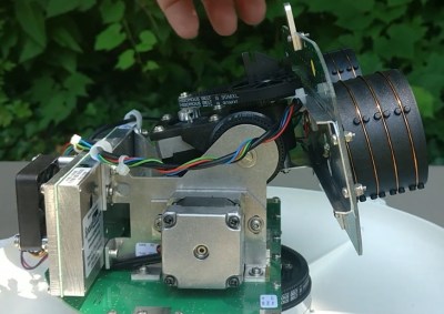
The build cribs from [Christine’s] earlier work on a VFD alarm clock, using similar tubes and driver chips to run the display. FM radio and amplification are courtesy of convenient modules. Tubes are fitted for aesthetic purposes, artfully lit with a smattering of color-changing LEDs. Perhaps the neatest touch is the use of valve handles to control tuning and volume. A stepper motor turns a series of gears, as is mandatory for any true steampunk build, and there’s even an electromagnetic actuator to make the Morse key move. To run it all, a pair of Arduino Megas are charged with handling the I/O needs of all the various systems.

It’s a fancy build that shows how far the rabbit hole you can go when chasing a particular look and feel. It’s a radio that would make a great conversation piece on any hacker’s coffee table.  If that’s not enough, consider going for a whole laptop. Video after the break.


via Radio Hacks – Hackaday https://ift.tt/2HA9xKX

Are Subcompact Pistols Worth It?

Wednesday, August 28, 2019

FM Signal Detection The Pulse-Counting Way

Compared to the simple diode needed to demodulate AM radio signals, the detector circuits used for FM are slightly more complicated. Wrapping your head around phase detectors, ratio detectors, discriminators, and quadrature detectors can be quite an exercise. There’s another demodulation method that’s not so common, but thankfully it’s also pretty easy to understand: the pulse counting detector.

As [Allan (W2AEW)] notes in the video below, pulse counting is a bit of a misnomer. Pulse counting works by generating a narrow, fixed-width square wave pulse at a set point in the received FM signal’s waveform, usually at the zero-crossing point. Since the frequency of the modulated carrier changes, the duty cycle of the resulting pulse train varies. That means there will be a fixed number of pulses, but by taking the average voltage of the pulse train, we can tease out the original audio frequency signal.

Simple in theory is often more complicated in practice, and [W2AEW] goes into some detail about those complications, such as needing to use a down-converter to make the peak-to-peak frequency deviation in the pulse train more easily detectable. As is his style, he walks us through a test circuit to prove that the theory works in practice. A simple two-transistor circuit generates the pulses at the zero-crossing point, a low-pass filter cleans up the signal, and a cheap audio amplifier reproduces the original audio. It’s a crude circuit to be sure, relying on the stray capacitance of the breadboard to work, but it proves the point and serves as a jumping-off point for further experiments – perhaps using an Arduino to count the pulses?

We always enjoy [W2AEW]’s videos and learn a lot from them. Not long ago we featured another of his videos talking about the mysteries of RF modulation; SSB, anyone?


via Radio Hacks – Hackaday https://ift.tt/2ZnWlnk

Introduction to Survival Fitness

Monday, August 26, 2019

Quantum Radar Hides In Plain Sight

Radar was a great invention that made air travel much safer and weather prediction more accurate, indeed it is even credited with winning the Battle of Britain. However, it carries a little problem with it during times of war. Painting a target with radar (or even sonar) is equivalent to standing up and wildly waving a red flag in front of your enemy, which is why for example submarines often run silent and only listen, or why fighter aircraft often rely on guidance from another aircraft. However, researchers in Italy, the UK, the US, and Austria have built a proof-of-concept radar that is very difficult to detect which relies upon quantum entanglement.

Despite quantum physics being hard to follow, the concept for the radar is pretty easy to understand. First, they generate an entangled pair of microwave photons, a task they perform with a Josephson phase converter. Then they store an “idle” photon while sending the “signal” photon out into the world. Detecting a single photon coming back is prone to noise, but in this case detecting the signal photon disturbs the idle photon and is reasonably easy to detect. It is likely that the entanglement will no longer be intact by the time of the return, but the correlation between the two photons remains detectable.

Of course, in reality they don’t use just a single photon. The process — known as quantum illumination — uses the weakened correlation and sampling to beat the performance of other techniques using the same number of photons and bandwidth.

Other than the quantum part, the rest of the setup is pretty simple to understand. The signal frequency is a little more than 10 GHz, while the idler is at almost 7 GHz. The receiver down converts to an intermediate frequency of 20 MHz and then uses a 100 MHz 8-bit A/D to grab the signal and do a Fourier transform.

Most of what we see involving quantum physics involves computing. We are still hoping [Sean] will work out his quantum coffee pot.


via Radio Hacks – Hackaday https://ift.tt/2NzRFDA

The Satellite Phone You Already Own: From Orbit, UbiquitiLink Will Look Like a Cell Tower

Thursday, August 22, 2019

Easy Direction Finding Thanks To Quad SDRs

Direction finding has long been a pastime of the ham radio community. Fox hunts and other DF events have entertained many, as they swept their antennas hunting for a transmitter. As with rock and roll and flared pants, time changes all things, and [Corrosive] has been experimenting with a very modern way to go about direction finding with SDR.

The work is made possible through the use of Kerberos SDR, a device which is essentially four RTL-SDR radios operating in unison. By fitting these with the appropriate antennas and running the right calibrations, the hardware can be used as a powerful direction finding tool.

[Corrosive] demonstrates this ably, by fitting the rig to his car and driving around on the hunt for a transmitter. Hunting for a P25 control station, he demonstrates the configuration of the hardware to help find the FM modulated signal. The software part of the equation is integrated with GPS maps, so one can follow the bearing towards the signal source while data is collected. Over time, the software takes more samples until it builds up an expected location for the transmitter.

The setup is remarkably effective, and largely does all of the heavy lifting, leaving the user to simply handle driving the car. The heat mapping feature is also incredibly cool, and would look great in your next spy movie. We’ve featured Kerberos SDR before, and fully expect to see more great work on this platform. Video after the break.


via Radio Hacks – Hackaday https://ift.tt/2ZbRF3Q

Thursday, August 15, 2019

Bike-Mounted Synthetic-Aperture Radar Makes Detailed Images

Synthetic-aperture radar, in which a moving radar is used to simulate a very large antenna and obtain high-resolution images, is typically not the stuff of hobbyists. Nobody told that to [Henrik Forstén], though, and so we’ve got this bicycle-mounted synthetic-aperture radar project to marvel over as a result.

Neither the electronics nor the math involved in making SAR work is trivial, so [Henrik]’s comprehensive write-up is invaluable to understanding what’s going on. First step: build a 6-GHz frequency modulated-continuous wave (FMCW) radar, a project that [Henrik] undertook some time back that really knocked our socks off. His FMCW set is good enough to resolve human-scale objects at about 100 meters.

Moving the radar and capturing data along a path are the next steps and are pretty simple, but figuring out what to do with the data is anything but. [Henrik] goes into great detail about the SAR algorithm he used, called Omega-K, a routine that makes use of the Fast Fourier Transform which he implemented for a GPU using Tensor Flow. We usually see that for neural net applications, but the code turned out remarkably detailed 2D scans of a parking lot he rode through with the bike-mounted radar. [Henrik] added an auto-focus routine as well, and you can clearly see each parked car, light pole, and distant building within range of the radar.

We find it pretty amazing what [Henrik] was able to accomplish with relatively low-budget equipment. Synthetic-aperture radar has a lot of applications, and we’d love to see this refined and developed further.

[via r/electronics]


via Radio Hacks – Hackaday https://ift.tt/2Z8I2Ou

Monday, August 5, 2019

Lucid Dreaming | Is it worth it to train prospective memory

Hello,

My apologies if this is a stupid question or has already been answered, I'm still getting accustom to searching this site.

I am wondering about whether or not it is worth while to train prospective memory if I have not yet identified any dream signs.

I am relatively new to this, but have been keeping a dream journal and practicing reality checks throughout the day. However, I am yet t to identify any dream signs, so I am wondering what the point to training prospective memory is if I don't have any dream signs to try to remember in my dreams.

Also if anyone has any tips about identifying dream signs I would love to hear them.

Cheers,
Shingles


via Lucid Dreaming - Dream Views - Attaining Lucidity https://ift.tt/31jkfwx

27 More Long-life Foods for Your Survival Plan

Sunday, August 4, 2019

L Band Satellite Antennas Revealed

[SignalsEverywhere] has a lot of satellite antennas and he’s willing to show them off — inside and out — in his latest video that you can see below. Using software-defined radio techniques, you can use these antennas to pull off weather satellite images and other space signals.

A lot of these antennas are actually made for some commercial purpose like keeping ships connected to Inmarsat. In fact, the shipborne antenna has a nice motorized system for pointing the antenna that [SignalsEverywhere] is hoping to modify for his own purposes.

With what appears to be standard NEMA 17 steppers onboard, it should be relatively easy to supplant the original controller with an Arduino and CNC shield. Though considering the resale value these particular units seem to have on eBay, we might be inclined to just roll our own positioner.

The QHF antenna is another interesting teardown. The antenna makes a helix shape and looks like it would be interesting to build from scratch. There isn’t a lot of details about the antenna designs, but it is interesting to see the variety and range of antennas and how they appear internally.

L band is from 1 GHz to 2 GHz, so signals and antennas get very strange at these frequencies. The wavelength of a 2GHz signal is only 15cm, so small antennas can work quite well and are often as much mechanical designs as electrical. The L band contains everything from GPS to phone calls to ADS-B.

We’ve seen radiosonde antennas reborn before. Dish antenna repurposing is also popular.


via Radio Hacks – Hackaday https://ift.tt/2Ks5RLI

Saturday, August 3, 2019

Antenna Tuning For GHz Frequencies

Antenna tuning at HF frequencies is something that radio amateurs learn as part of their licence exam, and then hone over their time operating. A few basic instruments and an LC network antenna tuner in a box are all that is required, and everything from a bit of wet string to ten thousand dollars worth of commercial antenna can be loaded up and used to work the world. When a move is made into the gigahertz range though it becomes a little more difficult. The same principles apply, but the variables of antenna design are much harder to get right and a par of wire snippers and an antenna tuner is no longer enough. With a plethora of GHz-range electronic devices surrounding us there has been more than one engineer sucked into a well of doom by imagining that their antenna design would be an easy task.

An article from Baseapp then makes for very interesting reading. Titled “Antenna tuning for beginners“, it approaches the subject from the perspective of miniature GHz antennas for IoT devices and the like. We’re taken through the basics and have a look at different types of antennas and connectors, before being introduced to a Vector Network Analyser, or VNA. Here is where some of the Black Art of high frequency RF design is laid bare, with everything explained through a series of use cases.

Though many of you will at some time or other work with these frequencies it’s very likely that few of you will do this kind of design exercise. It’s hard work, and there are so many ready-made RF modules upon which an engineer has already done the difficult part for you. But it does no harm to know something about it, so it’s very much worth taking a look at this piece.

It’s an area we’ve ventured into before, at a Superconference a few years ago [Michael Ossmann] gave us a fundamental introduction to RF design.


via Radio Hacks – Hackaday https://ift.tt/2YDzNhe